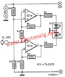
Using this circuit allow driving a bicolor LED that changes color light depending on the supply voltage. When voltage control circuit input range from 0 V to +12 V LED lights green at first and then pass gradually through orange and yellow to red.
The two sections of the bicolor LED (red and green) are ordered separately: the green IC1a by R7 and R8 red one with IC1b through.
 AO IC1b amplification is equal to 2, resulting in red LED lights starting from input voltage of about 0.5 V. This section illuminates to maximum brightness when Uin> Ub / 2.
IC1a AO is an inverting amplifier with gain equal to 2. Noninverting input is connected to a potential Ub / 2. When input voltage is less than Ub / 2's output is high level. When the input voltage rises above Ub / 2, Section green LED will light weaker, is completely extinguished when Uin = Ub.
The two sections of the bicolor LED (red and green) are ordered separately: the green IC1a by R7 and R8 red one with IC1b through.

IC1a AO is an inverting amplifier with gain equal to 2. Noninverting input is connected to a potential Ub / 2. When input voltage is less than Ub / 2's output is high level. When the input voltage rises above Ub / 2, Section green LED will light weaker, is completely extinguished when Uin = Ub.

No comments:
Post a Comment